It’s no secret I am a fan of Gitlab and I thought about ways to utilize their API/callbacks to create a fun project using Elixir/Nerves. Other companies have created their own versions of light based notifications, here’s my take on it.
Hardware
I am going to use a 3 color tower light from Adafruit to provide the visual aspect of the notification system. It will be controlled by a Raspberry PI Zero W or a Raspberry PI 3, the code can be shared between the two devices. A 4 channel 5v relay board will control turning the lights on and off via the GPIO. Power to the lamp requires the use of a barrel jack and a 12v power adapter.
The tower light requires constant 12v power and each lamp is illuminated by grounding the corresponding wire. Each color you turn on reduces the brightness of the remaining colors. I found you could power on green and red but yellow would be barely visible. For yellow to be bright it would need to be illuminated on its own.
Setting up the relay board
The relay board requires 5v (VCC) from the Raspberry PI, when shopping you need to double check the voltage required as some are higher and couldn’t be powered by the Raspberry PI itself. The board must be grounded and you should ground all your components to the GPIO ground, including the barrel jack.
The relay board has a male pin to connect to the specific GPIO pin that you wish to control it with. Relays are identified by IN1 through IN4 and each have a LED that illuminates when connected.

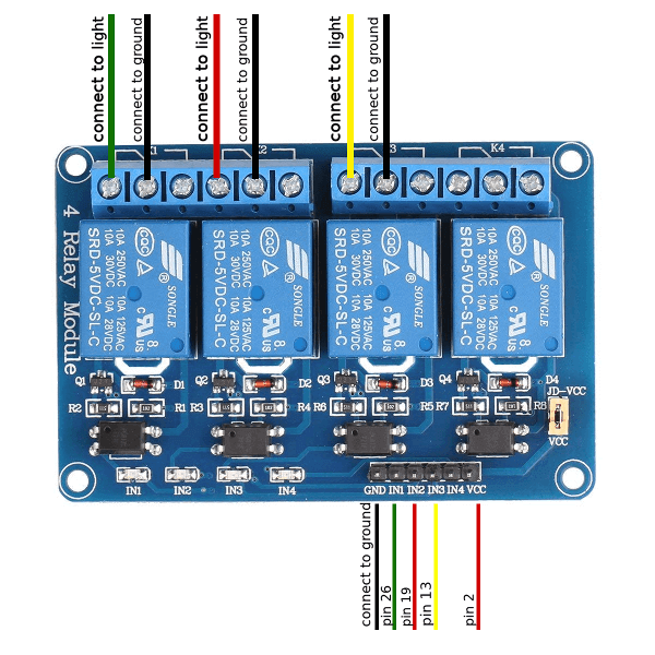
The table below details how to connect the Raspberry PI to the relay board and the color light it controls. I used this handy diagram for finding the GPIO pin numbers.
| Relay Label | GPIO Pin | Color |
|---|---|---|
| GND (ground) | 6 | _ |
| IN1 | 26 | Green |
| IN2 | 19 | Red |
| IN3 | 13 | Yellow |
| IN4 | _ | _ |
| VC (power) | 2 | _ |
Connecting the tower light
The relay board is going to allow the grounding of the lamp wires which will turn on the corresponding light. A single relay is required per light color you want to control. The alarm functionality of the light will not be used, it’s louder than you would expect!

ANormally Open terminal.Bis the Common terminalCNormally Closed terminal
I am going to use the Normally Open terminal configuration. When the GPIO goes high (3.3v) the switch closes and allows A and B to connect thus grounding the lamp to turn on the light. To turn the light off the switch is opened when the GPIO goes low (0v). For a better explanation of how relays work, visit this site.
Each of the three relays used will have the B terminal connected to a common ground. The A terminal will be connected to the colored wire of the light you want that relay to control.
Powering the tower light
The 12v from the barrel jack is connected to the brown wire of the tower light. Next the ground from the barrel jack is connected to the ground on the Raspberry Pi. Another reminder to use a common ground for all components.
What does GPIO low and high mean?
In case GPIO low and high are new terms, I’ll describe them. Having a pin in the low state results in the pin outputting 0v while having a pin in the high state (in the case of a raspberry pi) outputs ~3.3v. It’s also worth noting that the pins can be in an output state or an input state. For this project we will be using the output state.
Controlling GPIO pins using Elixir
Seeing concepts represented in code should make what I describe above a bit more real. For this example I will be using the circuits_gpio library.
First the GPIO pin must be opened in output mode, pin 26 is one of the relay inputs specified previously and controls the green light. To turn the light on the pin is set to 1 which is HIGH. To turn the light off the pin is set to 0 which is LOW.
{:ok, green} = Circuits.GPIO.open(26, :output)

# Sets the GPIO pin to HIGH which turns ON the light
Circuits.GPIO.write(green, 1)

# Sets the GPIO pin to LOW which turns OFF the light
Circuits.GPIO.write(green, 0)

Circuits.GPIO.close(green)
Software
Part 2 will detail the source code required to receive Gitlab callbacks for CI events on the Raspberry PI.
Thank you for reading about how to build a Gitlab CI light using Elixir/Nerves. If you have any questions/comments please reach out on Twitter or ElixirForum!